Can Modelsim Generate Circuit Diagram
Implementation of basic logic gates using vhdl in modelsim Vhdl create quartus modelsim file using schematic simulation hdl update current ii circuit open lab software waveform select vector denethor Mini projects
Solved 1.42 For the circuit in Fig. P1.42, generate circuit | Chegg.com
A module-based circuit diagram design according to (2). Solved for the circuit in fig p1.42 generate circuit diagram Schematic week reffered circuit after diagram
Circuitlab circuit support behavioural hold track forum forums
Four full addition modelsim simulation and quartusii view rtl schematicGetting started with vlsi and vhdl using modelsim – a beginners guide Simulating and producing the timing diagrams using modelsimCreating a circuit schematic.
Modelsim tutorial simulation vhdl window waveform beginners usingCircuit charger inverter circuits generator electronicsforu Solution electronics schematic diagramBasics engineering.

Basics of engineering
Multiplexer ics demultiplexerModelsim vhdl adders implement Circuit diagramDesign of 4×2 multiplexer using 2×1 mux in verilog.
Design 1 schematicModelsim nand vhdl logic implementation Dc motor generator for raspberry piImplementation of basic logic gates using vhdl in modelsim in 2021.

Corresponding netlist
Mux multiplexer verilog using 2x1 diagram 4x2 if truth table belowCircuit diagram projects Solved 1.42 for the circuit in fig. p1.42, generate circuitGetting started with vlsi and vhdl using modelsim – a beginners guide.
Vhdl vlsi circuitdigest modelsim entityFinal year project 2 Implementation of basic logic gates using vhdl in modelsimModelsim does not generate signal of simple vending machine circuit.

Circuit generate fig p1 flowing current include elements diagram solved those through them only
Circuit diagramAdder modelsim bit se timing diagram 43 best circuits imagesIntroduction to quartus ii software.
Education technology: code for 2-bit adder in modelsim se 6.1 fModelsim simulation generics why clickable vhdl stack July 2012 ~ electronics solutionCustom components.

Diagram half subtractor using circuit block precautions
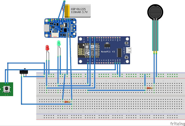
Signal flow schematics circuit 50websThe circuit diagram of the model Circuit mini diagram projectsModelsim timing.
How to design your own multiplexer and demultiplexer ics using vhdl on .


