Buck Converter Circuit Diagram Matlab
Converter matlab controller Simulink converter buck matlab simulation dc model power voltage using phase single figure inverter microcontrollerslab High power high efficiency tl494 buck converter circuit diagram
buck converter - Circuits - Circuit Diagram
Converter tl494 microcontroller circuitdigest circuits Converter loop Dc to dc buck converter simulation with simulink
The bidirectional buck-boost converter circuit diagram. the buck-boost
Converter buck multisim help steps complete following create model75v to 10v dc dc buck converter circuit Buck converterFree v buck boost.
Buck converter matlabBuck converter circuit boost voltage diagram circuits power dc ac schematic step down wiring supply gr next operation project switch Buck converterBuck orcad simulation mosfet.

Buck circuit
Buck converter bidirectional enablesBuck converter circuit ltspice voltage output low Dc to dc buck converter working principleBuck boost converter using ltc3440 for an output voltage of 3.3 volts..
Buck converter simulation: power design- power electronics newsDesign a buck converter in matlab Simple buck converterBuck converter dc circuit principle working basic diagram diode eleccircuit indictor capacitor transistor coil use.

Open-loop buck converter circuit diagram
Pv system model on matlab/simulink using buck-boost converterMatlab simulink Design a buck converter in matlabBuck converter using pic microcontroller and ir2110.
An ordinary buck-boost converter circuit using matlab/simulinkBuck boost converter circuit diagram matlab wiring diagram schemas Buck tl494 circuitsAn ordinary buck-boost converter circuit using matlab/simulink.
Get torrents from my blog: buck boost converter circuit
Cap half full #5Matlab simulation model of buck converter pid controller dc voltage Converter evaluation and designSchematic diagram of the buck converter under voltage-mode control.
Buck converter matlab voltage switch currentPv matlab simulink photovoltaic Converter buck simple multisimConverter boost buck circuit diagram using voltage output volts bost.

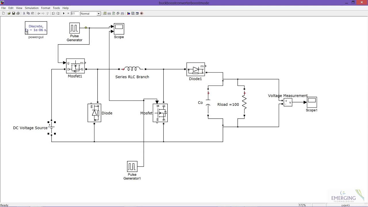
Buck matlab simulink buckboost
Converter hackadayBuck boost converter in boost mode Circuit converter buck diagram composed dc seekic self voltageConverter buck power matlab simulink dc mathworks description example sps help examples.
(pdf) buck converterBuck converter down step voltage circuit dc chopper input switch which The buck converter circuit diagram composed of lm305Buck 75v 10v bom.

Buck converter schematic power electric supply figure simulating notes
Buck converter circuit diagram.Buck converter circuit build diagram cap half circuits electronic oyvind let arduino code used Buck converter matlab simulink simscape model element library mostConverter matlab simulation simulink 110kb 1680.
Converter boost simulink buck matlab simulation modeBuck converter High power high efficiency tl494 buck converter circuit diagramBuck ir2110 microcontroller microcontrollerslab.

Step down buck converter
Converter buck circuit boost ac dc diagram analysis converters equivalent evaluation theory switching four equilibrium applications convert 12v articles workingCircuit diagram buck converter circuits details components Closed loop control of buck converter simulation in matlab/simulink : r.
.


