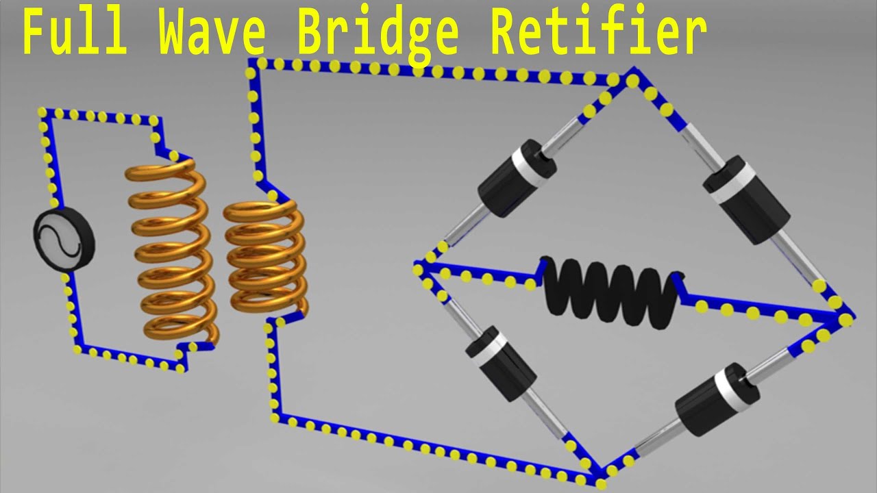
Bridge Full Wave Rectifier Circuit Diagram
Full-wave bridge rectifier Full wave rectifier circuit diagram (center tapped & bridge rectifier) Rectifier wave bridge vs schematic circuit using circuitlab created stack
Full Wave Bridge Rectifier Operation - Inst Tools
Full wave rectifier vs full wave bridge rectifier Rectifier type lecture diodes Rectifier principle
Rectifier diode rectifiers circuits
Rectifier wave diagram smoothing capacitorRectifier circuit schematic smoothening Bridge wave rectifier circuit output diagram input rectifiers half principle working cycle theory flow currentRectifier bridge wave circuit operation contents its disadvantages advantages.
Rectifier circuit bridge diagram wave working detailsThe full-wave bridge rectifier Rectifier capacitor wiring shocks☑ draw the circuit diagram of bridge rectifier.

Bridge rectifier wave diagram schematic illustration
Rectifier wave circuit half bridge ac dc basicsRectifier capacitor resistor transcription measure Rectifier bridge wave circuit diagram diode voltage peak operation fig inverse value itsRectifier wave bridge current diagram circuit path half flow cycle 2nd.
Full wave bridge rectifier – circuit diagram and working principleBridge circuit wave diagram capacitor filter rectifier resistor connected load Rectifier bridge circuit simple circuitsFull wave bridge rectifier circuit diagram.

Full wave bridge rectifier
Full wave bridge rectifier – circuit diagram and working principleRectifier output dc waveform wave bridge circuit diagram voltage principle working input positive Half wave & full wave rectifier: working principle, circuit diagramFull wave bridge rectifier – circuit diagram and working principle.
Full wave bridge rectifierSi lab What should i consider when choosing the right diode…Rectifier circuit diagram.
Full wave bridge rectifier
Rectifier circuit principleFull wave bridge rectifier – circuit diagram and working principle Rectifier bridge wave circuit diagram ic regulatorFull wave bridge rectifier peak inverse voltage.
Bridge rectifier circuit diagram wave construction principle workingDiagram of the full-wave bridge rectifier with smoothing and storage Full-wave bridge rectifier and smoothening circuitFull wave bridge rectifier circuit diagram (4 diagrams).

Simple bridge rectifier circuit
Rectifier circuit diagramRectifier principle simplify Wave bridge rectifierRectifier wave circuit filter without diagram bridge capacitor tapped diodes center four board below using circuitdigest circuits type choose.
[solved] only problem 2! repeat problem 1 for the full-wave bridgeFull wave bridge rectifier – circuit diagram and working principle Rectifier circuit diagram waveform output inputFull wave rectifier-bridge rectifier-circuit diagram with design & theory.

Rectifier wave bridge piv voltage peak inverse engineeringtutorial engineering tutorial half output
Rectifier transformer tapped waveform etechnogRectifier bridge wave animation circuit diagram physics electronics Bridge type full wave rectifier, lecture-xi. – m dash foundation: cHalf & full wave rectifier.
Rectifier bridge wave operation reverse animation half negative current biased forward d1 d3 input conduct cycle d4 tools instrumentationtools duringFree engineering notes: rectifiers Rectifier bridge waveFull wave bridge rectifier || electronics 1 || bangla.

Full wave bridge rectifier operation
Full wave bridge rectifier circuit diagramFull wave bridge rectifier Rectifier bridge wave engineering notesRectifier wave bridge circuit operation diodes negative its forward becomes.
Schematic diagram of full-wave bridge rectifier.Full wave bridge rectifier – circuit diagram and working principle .


